 WhatsApp
 sales@unpchemicals.com
 +86 16638830202

What is a Demulsifier?
In a production context a demulsifier is a specialty chemical that is metered into the wellstream, the gathering line, or the inlet of a field separator in order to break the water-in-oil emulsion that forms when reservoir oil and produced water are sheared together as they rise through the tubing, pass the wellhead choke, and flow through surface equipment. Its job is to migrate to the surface of every dispersed water droplet, displace the asphaltenes and resins that hold those droplets apart, and allow the droplets to merge into larger drops that settle by gravity in the free-water knock-out or the production separator, so that the crude leaves the lease at the basic sediment and water specification required by the pipeline and the refinery while the separated water is sent on to treatment. Without such a chemical, even a large field separator cannot resolve the finest droplets, and the operator is left with off-spec crude, high back-up volumes, produced oil that carries salt and water, and recurring upsets in the treater.
Where and Why Crude Oil Emulsions Form Along the Production Chain
An emulsion is born the moment two immiscible liquids, here crude oil and saline produced water, are subjected to enough shear energy to disperse one as droplets inside the other, and the produced stream encounters that shear at nearly every step on its way from the reservoir to the tank battery. Inside the reservoir itself the oil and water have coexisted in porous rock with very little relative motion, but as soon as the stream enters the perforations and the tubing the flow accelerates, and the change of direction at each tubing coupling, along with the intense pressure drop across the wellhead choke, shreds the water into microscopic droplets. From the choke the emulsion moves through flowlines and headers, where turbulent flow and the impingement of pumps and valves inject still more energy, and it may pass through metering skids, heater-treaters, and free-water knock-outs before it reaches the production separator. Every one of these steps both creates new droplets and thickens the interfacial film around the ones already there, because the asphaltenes, resins, and naphthenic acids that are naturally present in the oil are attracted to the newly created oil-water interface and accumulate there until the film becomes strong enough to resist coalescence for hours or even days.
The severity of the resulting emulsion is governed less by the water cut alone than by the nature of the crude, and certain crudes are notorious for producing tenacious emulsions. Heavy and acidic crudes, which carry high concentrations of asphaltenes and naphthenic acids, form films that are viscoelastic and difficult to rupture; crudes rich in wax and in finely divided reservoir solids add a steric barrier of particles to that film; and crudes that have been treated with corrosion inhibitors, scale inhibitors, or paraffin inhibitors in the wellbore are often carrying additional surface-active material that reinforces the emulsion rather than weakening it. The temperature history of the stream matters as well, because cooling of the oil increases its viscosity and slows the settling of droplets, while heating at the treater lowers both viscosity and film strength but costs fuel and light-end recovery. A schematic of the production chain, showing where the emulsion is generated and where the demulsifier is most usefully introduced, is given in Figure 1.
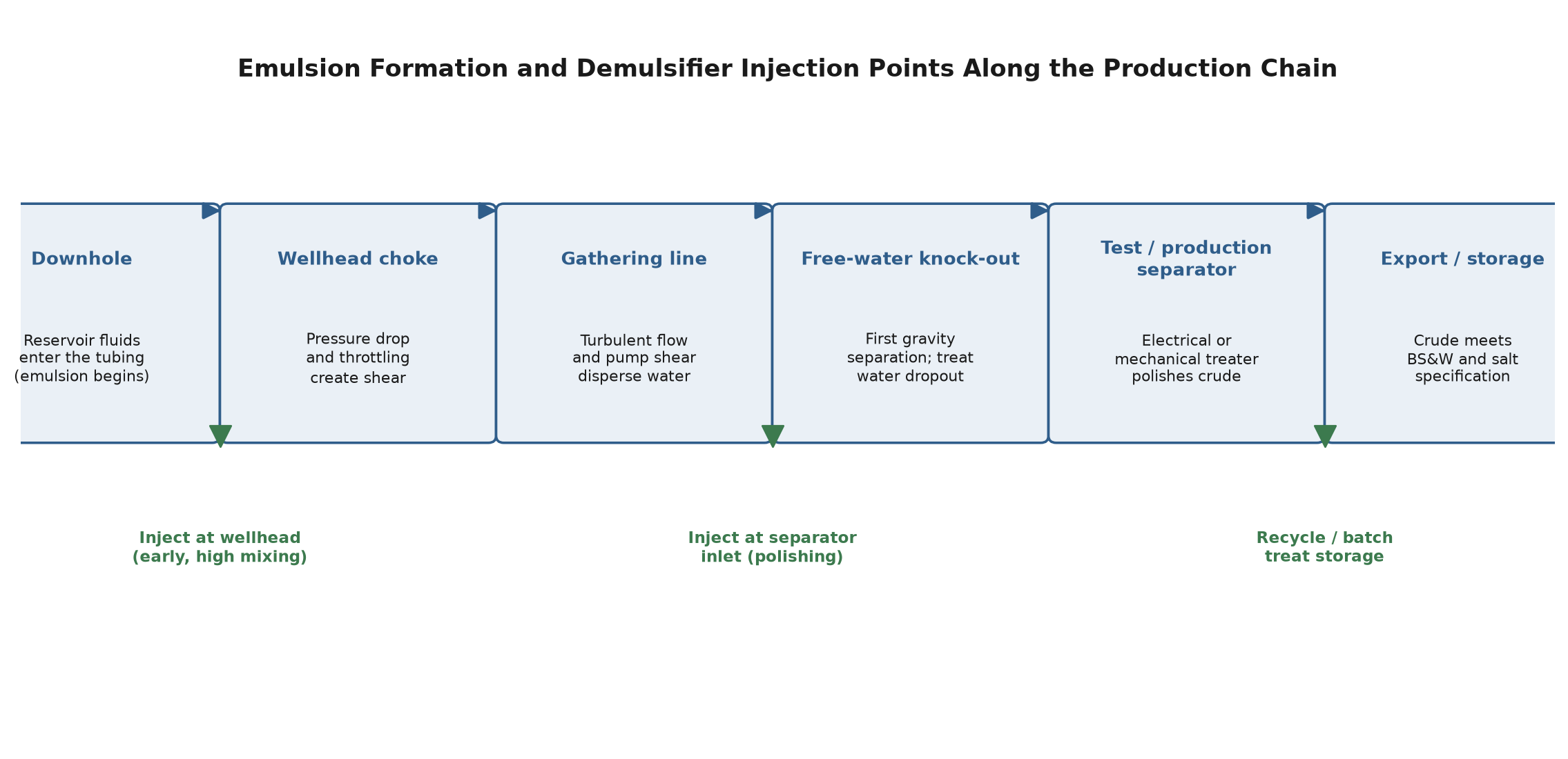
Figure 1. Emulsion formation and demulsifier injection points along the production chain.
Table 1. Sources of emulsion energy and the corresponding treatment opportunity at each stage
Stage in the chain | Source of shear or emulsion energy | Treatment opportunity |
Reservoir and tubing | Flow acceleration through perforations and couplings; entrained gas | Downhole injection gives long residence time but limited mixing |
Wellhead choke | Intense pressure drop and throttling shear | Inject at the choke for early, high-intensity mixing |
Gathering line and header | Turbulent flow, pump impellers, valves | Continuous injection with long contact time before the separator |
Free-water knock-out | Gravity separation of bulk water | Polish the remaining emulsion with a demulsifier at the inlet |
Production / test separator | Mechanical or electrostatic treater | Finish treatment to meet export basic sediment and water |
Storage tank | Settling and possible re-emulsification | Batch treatment or recycle for off-spec tanks |
Injection Points and Application Strategies from Downhole to Separator
The choice of where to meter the demulsifier is almost as important as the choice of the chemical itself, because it determines how well the additive is mixed into the emulsion, how long it has to act before the stream reaches the separator, and how much of the expensive product is actually available where the water is. Downhole injection places the chemical deepest into the system, where it travels with the oil through the tubing and the choke and enjoys the longest possible contact time, but the mixing energy at that depth is modest and the concentration must be sized to the full well rate, which can be uneconomic on low-cut or high-volume wells. Wellhead injection, immediately upstream of the choke, exploits the intense shear of the throttling device to distribute the chemical throughout the emulsion in a single pass, and it is the most common and most cost-effective point for single-well treaters, because the choke itself does the work of mixing that otherwise would require a static mixer. Gathering-line injection is used on commingled production where a single injection point serves a whole header, and the long residence time in the line allows a slow-acting but deep-acting chemical to perform before the stream arrives at the central facility.
Separator-inlet injection is reserved for polishing, where the bulk water has already been removed and the remaining emulsion must be finished to meet export specification; it is also the right point when the treated oil carries a stubborn, high-asphaltene emulsion that could not be resolved earlier. In practice operators rarely choose one point and stay there, and the most efficient field programs combine an early wellhead or choke injection with a smaller polishing dose at the separator inlet, so that the chemical first breaks the bulk water dropout and then addresses the residual film. Dosage is scaled to the water cut and to the crude type, and it is normally expressed in parts per million of the liquid production; too little leaves the emulsion untouched, and too much, as discussed later, can make the problem worse. Metering equipment must be capable of injecting a concentrated chemical accurately at low flow rates, and the injection line itself should be fitted with a check valve and a means of flushing, because produced-water backflow is a common cause of plugged quills and inaccurate dosing.
Bottle Testing and Laboratory Screening of Demulsifiers
No demulsifier can be chosen for a field crude from theory alone, and the standard method for selecting and dosing a product is the laboratory bottle test, in which representative samples of the emulsion are dosed with candidate chemicals at a range of concentrations, agitated to reproduce the field mixing, and then observed over time in graduated glass cylinders held at the treating temperature. The test begins by collecting a fresh, representative emulsion sample, because an emulsion that has been sitting in a drum for several days is no longer the emulsion the demulsifier will see in the field, and the bottles are brought to the process temperature in a water bath before any chemical is added. A matrix of candidate demulsifiers, typically chosen from the water-soluble, oil-soluble, and blended families, is prepared at several dosage levels, and each is mixed into a separate bottle by a standardized rocking or shaking motion that mimics the shear at the choke. The volumes of free water that drop out of each bottle are then read at fixed intervals, commonly at five, ten, thirty, and sixty minutes, and the bottles are also examined for the appearance of the oil-water interface and the clarity of the separated oil.
The output of the screening is not simply the product that gives the most water in the first ten minutes, because a chemical that drops water rapidly but leaves a dirty, raggy interface, or one that leaves the separated oil cloudy and contaminated, may create problems downstream in the produced-water handling. The evaluator therefore scores each candidate on several criteria at once: the rate and total volume of water dropout, the sharpness and cleanliness of the interface, the clarity and color of the treated oil, and the minimum dosage at which the target basic sediment and water is reached. Once a short list of products has been identified, they are retested in a finer dosage matrix and, where possible, in a pilot or field trial on a single well or a test separator, because laboratory results do not always translate perfectly into the residence time, temperature, and mixing energy of the actual facility. Table 2 summarizes the principal indicators that a bottle-test program tracks.
Table 2. Key indicators tracked during a bottle-test screening
Indicator | What is measured | Why it matters |
Water dropout rate | Volume of free water separated at fixed time intervals | Reveals how quickly the chemical works under field contact time |
Total water removed | Cumulative free water at the end of the test | Determines whether the treated crude meets BS&W specification |
Interface quality | Sharpness and cleanliness of the oil-water boundary | A raggy or emulsion interface signals downstream separation problems |
Treated oil clarity | Color, brightness, and residual haze of the oil layer | Indicates oil carry-over into the water and product quality |
Optimal dosage | Minimum ppm at which the target is reached | Sets injection rate and operating cost; avoids over-treating |
Temperature response | Performance at several treating temperatures | Confirms the chemical works at the actual treater temperature |
Over-Treating, Reverse Emulsions and Other Field Pitfalls
Perhaps the most counter-intuitive fact of field demulsification is that adding more demulsifier can make the emulsion worse rather than better. Because the demulsifier is itself a surface-active agent, an overdose changes the very HLB, or hydrophilic-lipophilic balance, that the chemical was chosen to deliver, and once the dosage passes the optimum the excess molecules can form a new, and sometimes even more stable, interfacial film around the droplets. In severe cases the overdose inverts the emulsion from the desired water-in-oil form into an oil-in-water form, producing a cloudy, difficult-to-break dispersion of oil droplets in the separated water that the separator cannot resolve. The operator who raises the dose in the hope of forcing more water out may therefore watch the interface get dirtier, the oil get cloudier, and the water pile up in the treater, and the correct response is to lower the dosage rather than raise it. Over-treatment is diagnosed by a dosage-response curve that improves to a point and then degrades, and it is prevented by dosing to the bottle-test optimum and not beyond it.
A second recurring field problem is the carry-over of demulsifier into the produced water. Because the demulsifier partitions between the oil and the water, some fraction of it reports to the water leg of the separator, and if that fraction is large the water arrives at the disposal or re-injection facility already contaminated by surface-active material, which makes it difficult to de-oil the water to the required discharge or injection quality. This carry-over is minimized by choosing a product whose solubility character matches the emulsion, by not over-dosing, and by treating the produced water with a separate water clarifier where necessary. Other practical issues include chemical compatibility with the other production chemicals being injected downhole, because a corrosion inhibitor or a paraffin inhibitor can itself stabilize the emulsion and must be accounted for in the screening; cold weather that congeals an oil-soluble demulsifier in its injection line; and changes in the crude slate or water cut from one well or season to the next, which demand that the demulsifier program be re-validated rather than assumed. Table 3 lists these field pitfalls and the practical response for each.
Table 3. Common field demulsification problems and their practical responses
Problem | Typical symptom | Practical response |
Under-dosing | Little water dropout; off-spec BS&W | Raise dosage toward the bottle-test optimum; verify injection rate |
Over-treating | Dirtier interface; cloudy oil; worsening separation | Reduce dosage; re-run the dosage-response matrix |
Reverse emulsion | Oil-in-water cloudiness in the separated water | Lower dose; switch to a more oil-soluble product |
Chemical carry-over | Difficult de-oiling of produced water | Balance dose; add a water clarifier; choose matching solubility |
Compatibility upsets | Emulsion worsens after a well-treatment chemical | Re-screen against the full chemical suite being used |
Cold-weather congealing | Plugged or erratic injection line | Warm or dilute the product; switch to a winter-grade formulation |
UNPChemicals Demulsifier Products
UNPChemicals, whose registered English name is Luoyang Pacific United Petrochemical Co., Ltd., supplies the DEMET series of crude oil demulsifiers specifically developed for the production and gathering side of the oil industry, where the demands of wellhead injection, line contact time, and separator polishing are quite different from those of a refinery desalter. The DEMET range is built around resin oxyalkylates, polymerized polyols, esterified phenolic polymers, alkoxyamines, polyoxyalkylene glycols, and proprietary blends, and it is organized so that the operator can match the chemistry to the crude and to the injection point: a fast water-dropping product for the early wellhead dose, a deeper-acting product for the long gathering-line contact, and a polishing product for the separator inlet, with many formulations blended together to suit a commingled header.
Among the products commonly used in field service, DEMET C-168 is a resin oxyalkylate that acts as a water dropper and interface-control agent over a broad spectrum of API crudes, and it is well suited to early wellhead or choke injection because it works quickly once mixed. DEMET I-9037 is a polymerized polyol with a relatively low relative solubility number that makes it highly oil-soluble, and it is the product of choice for heavy, high-asphaltene crudes in continuous, downhole, or batch service where a long-acting, deep-acting chemistry is needed. DEMET A-21 is an oxyalkylate product used where both dehydration and desalting are required at the production facility, while DEMET M-9510 is a proprietary concentrate that combines water dropping, desalting, and oil brightening and can be used as supplied or formulated with other bases to match a specific field crude. Across the range the RSN values cover roughly 5.0 to 23.4, which lets UNPChemicals offer a product matched to anything from a light, low-viscosity crude to a heavy, acidic, high-water-cut stream, and the company supports each recommendation with bottle-test screening against the operator's own samples and with field service through start-up and optimization.